
Before beginning the process of camera matching a photo, it’s imperative to be aware of the following:
1- Have an almost accurate dimension of a relevant object in the photo (e.g. at least one object in the photo)
2- Be aware that photos are usually taken at eye level (e.g. 1.65 meters); unless stated otherwise
3-The average height of most people in photos is between 1.70/1.75 meters; unless there’s an exception
4-The average door height is around 2.2 meters; unless there’s an exception
5-The average height of a chair is about 0.4 meters; unless there’s an exception
Start by setting up the Output size to match the incoming background photo to be camera matched.
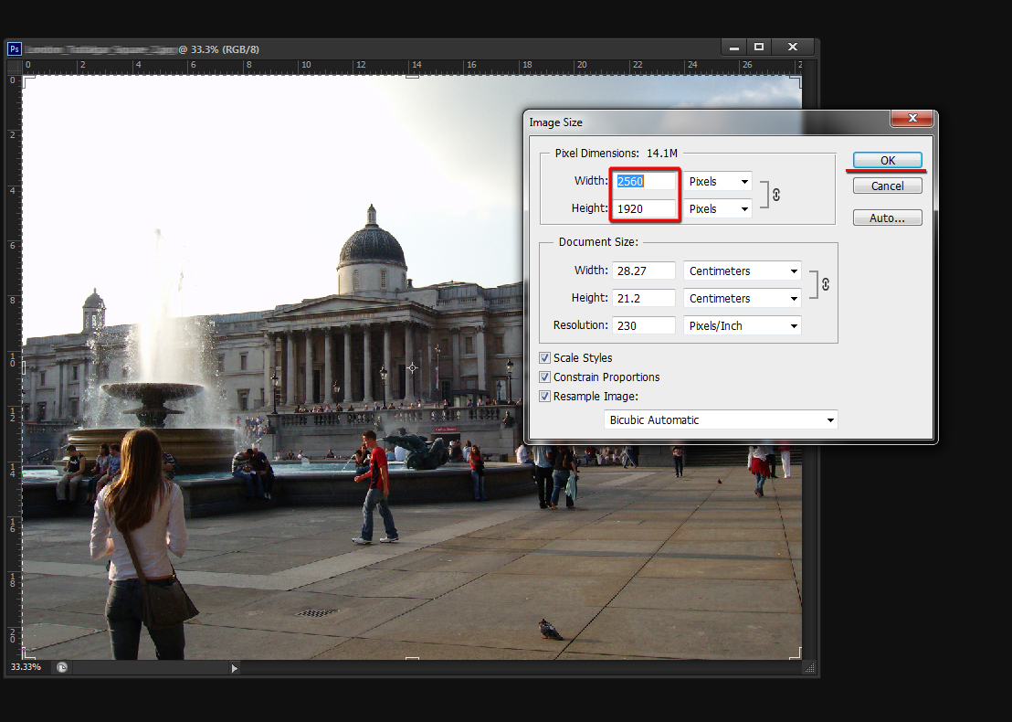
Background photo Image Size
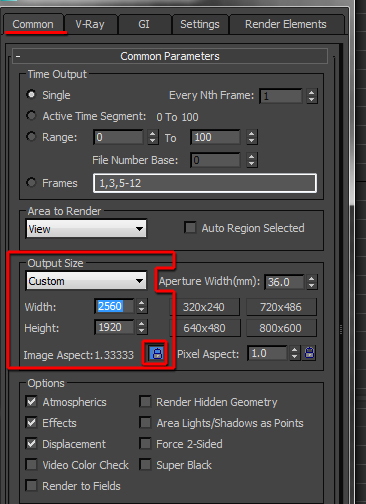
Output Size in 3ds Max
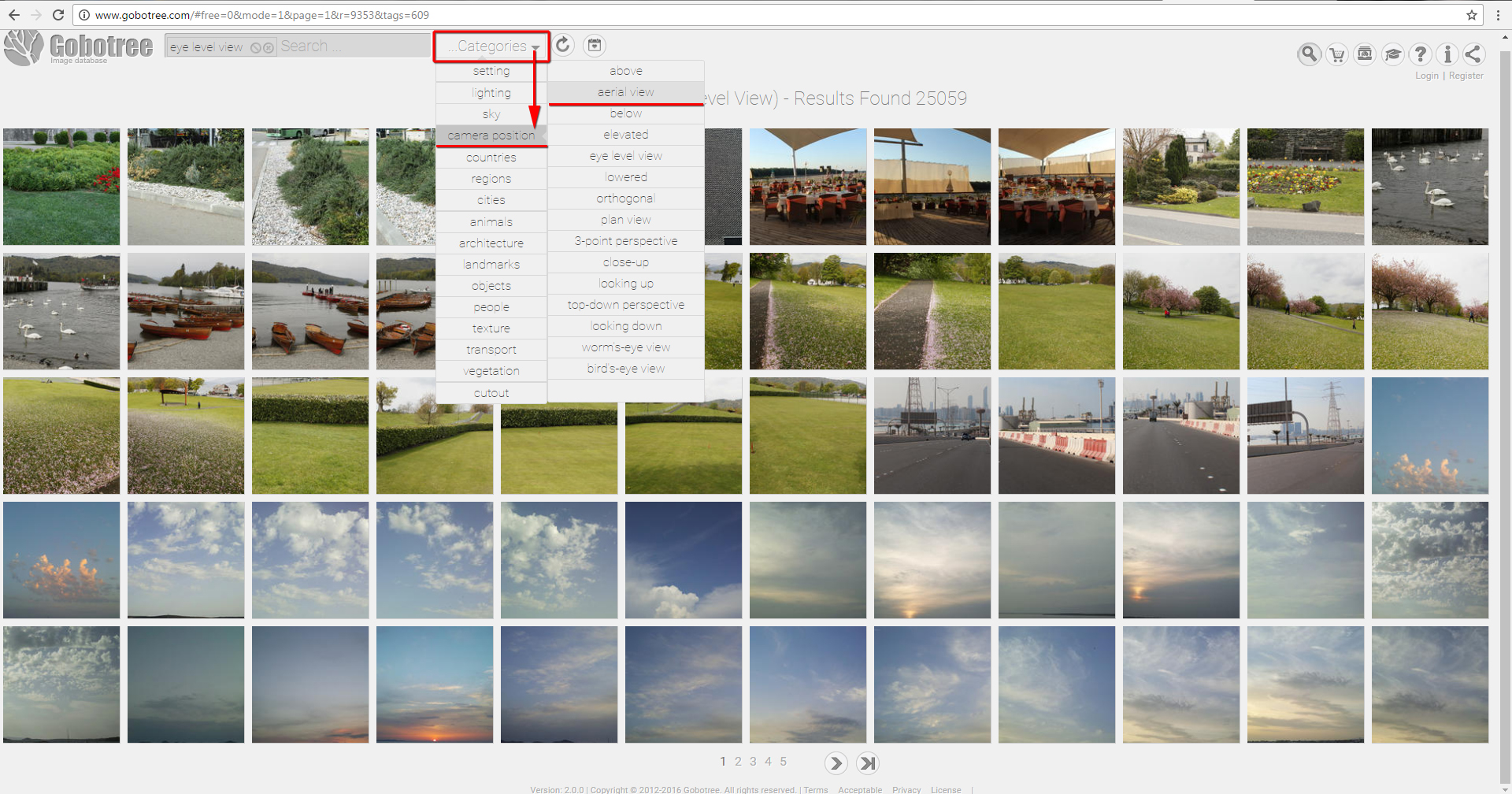
Gobotree photo library
Next, load up the background photo in the perspective viewport and use the Shift+F to enable the Show Safe Frames option.
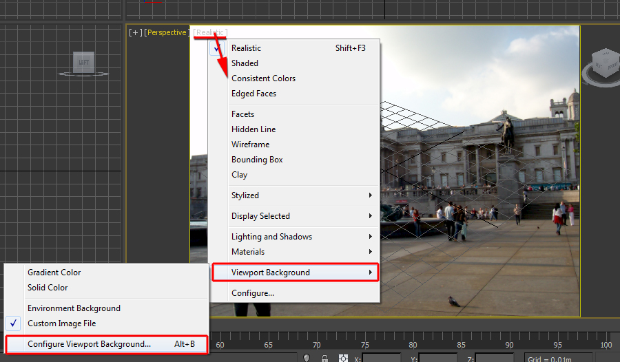
Load up the background photo in the perspective viewport
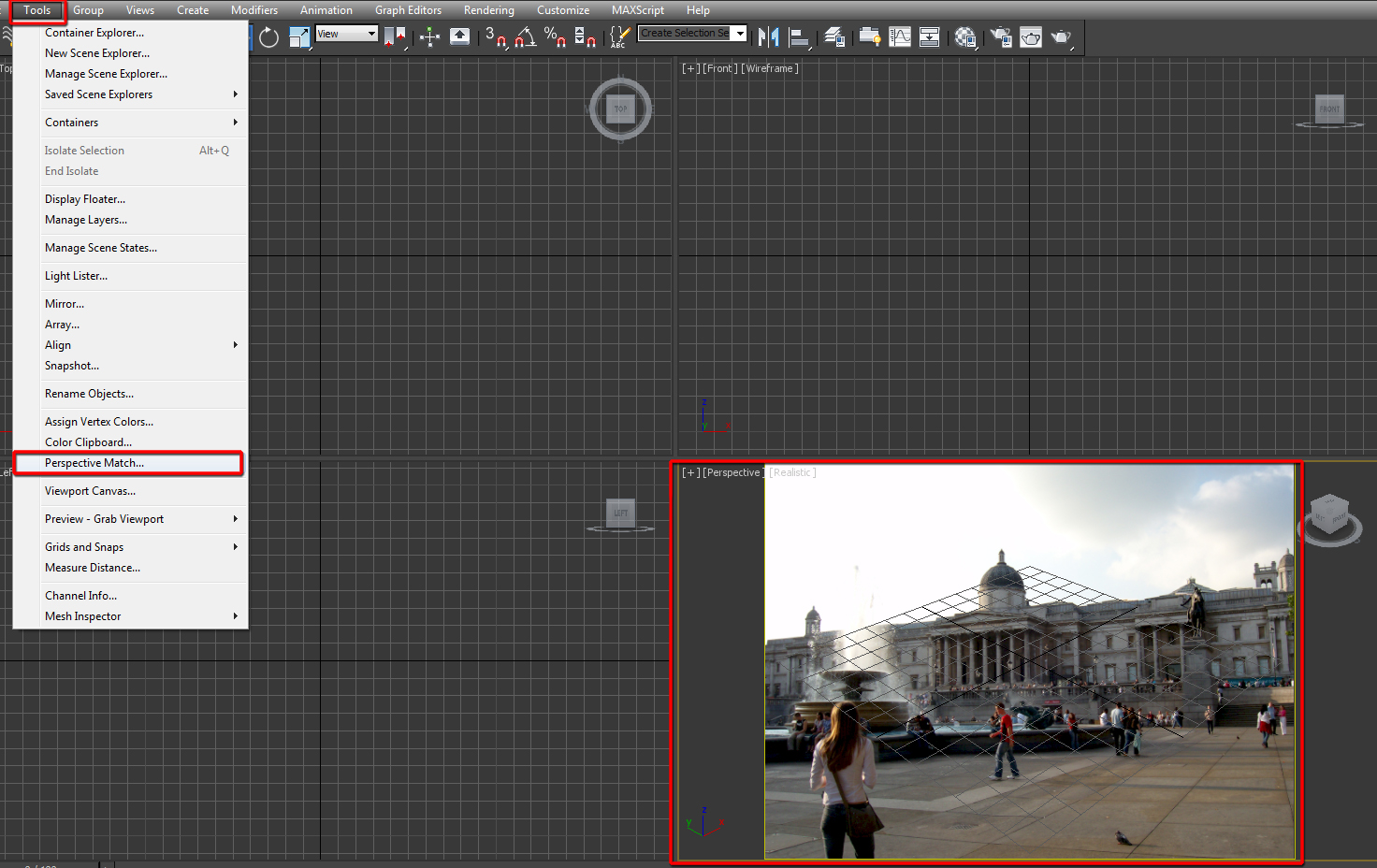
While the perspective viewport is still selected, click on the Tools from the main toolbar, followed by choosing the Perspective Match option.
The Perspective Match from the Utilities command panel should be prompted automatically. Click on the Hide Vanishing Lines button to make it visible in the viewport.
Select the Perspective Match tool
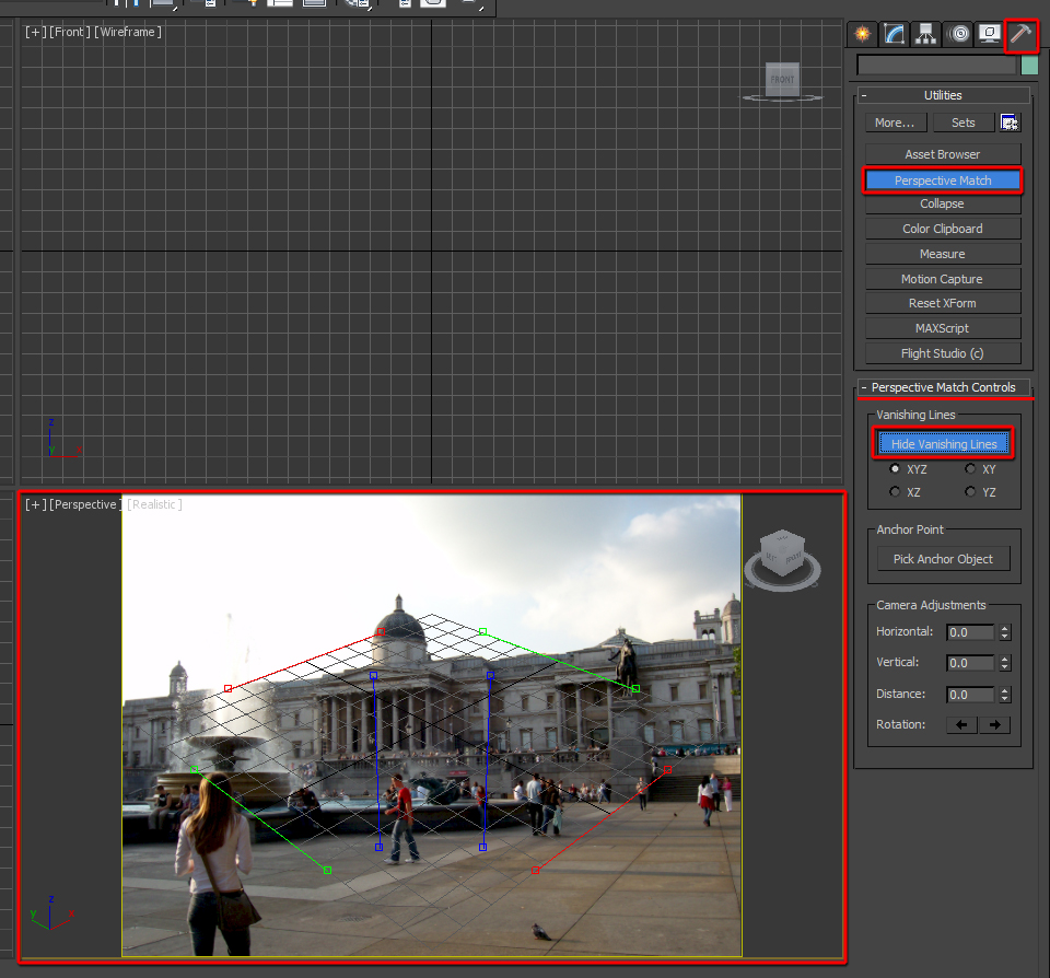
Click on “Hide Vanishing Lines” button to make it visible
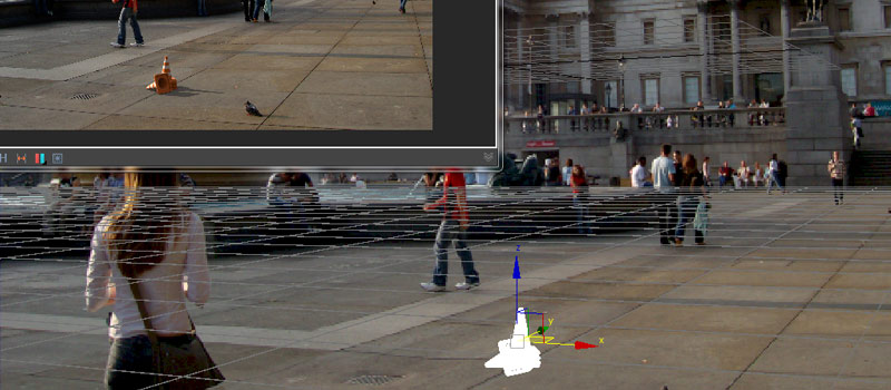
The two Blue Vanishing lines are usually moved to line up closely to two key horizontal lines of the photo
The two Green vanishing lines are often moved to line up closely to two key perspective lines of the photo (e.g. bottom/foreground and a top perspective line) .
The two Red vanishing lines are often moved to line up closely to two key horizontal lines of the photo
To move a vanishing line as a whole, simply left click on its middle point, followed by moving it.
To move parts of the vanishing line, simply click on one of its handles and move it accordingly.
The rule of thumb is to keep the top vanishing lines (e.g. red and green) on upper areas of the photo; and the lower vanishing lines (e.g. red and green) on the lower areas of the photo.
After much pulling and moving the vanishing lines around, the result should look similar to the figure depicted below.
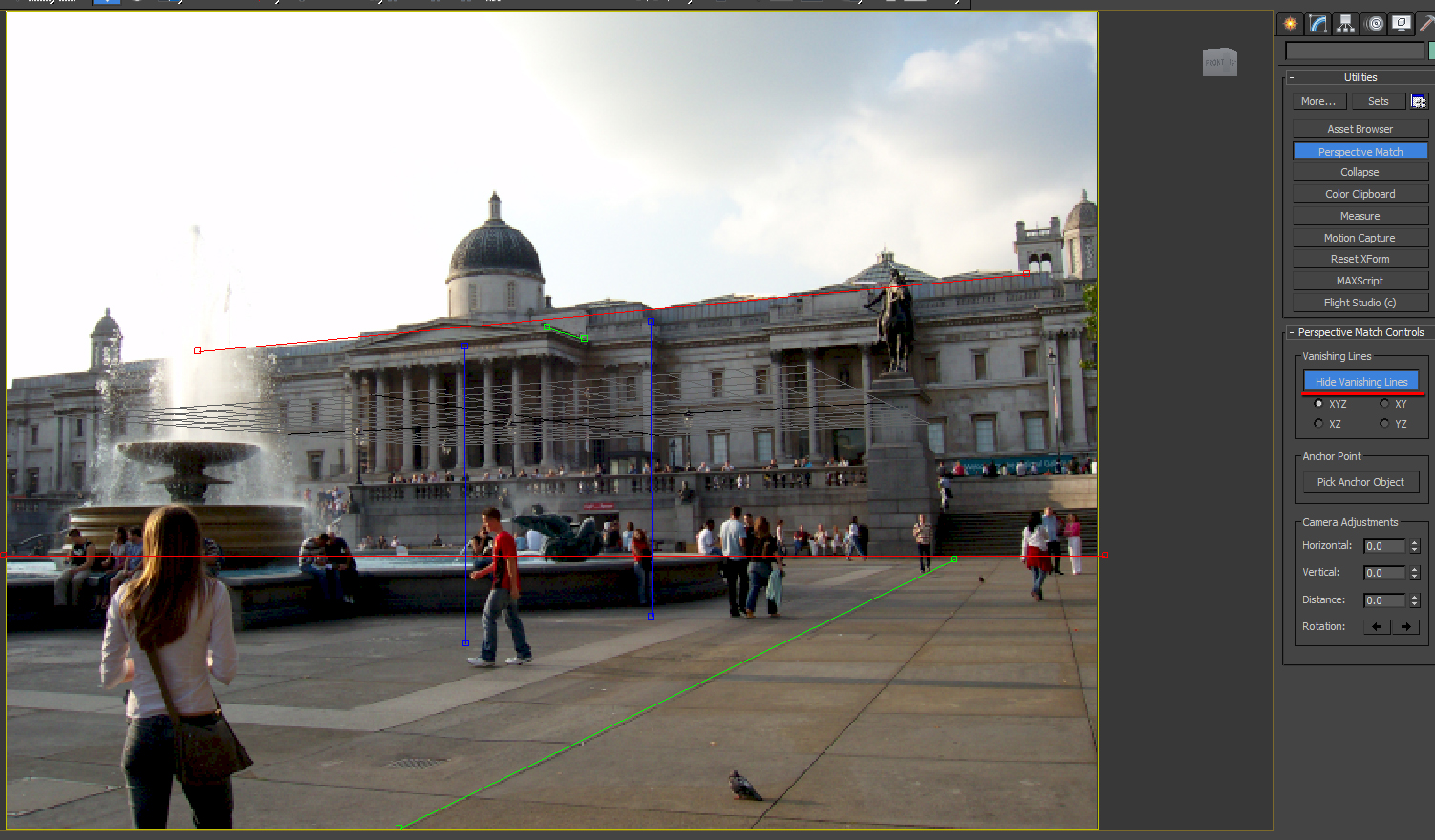
Vanishing lines lined up
Once satisfied with the position of the vanishing lines, simply Create Camera From View (Ctrl+C)
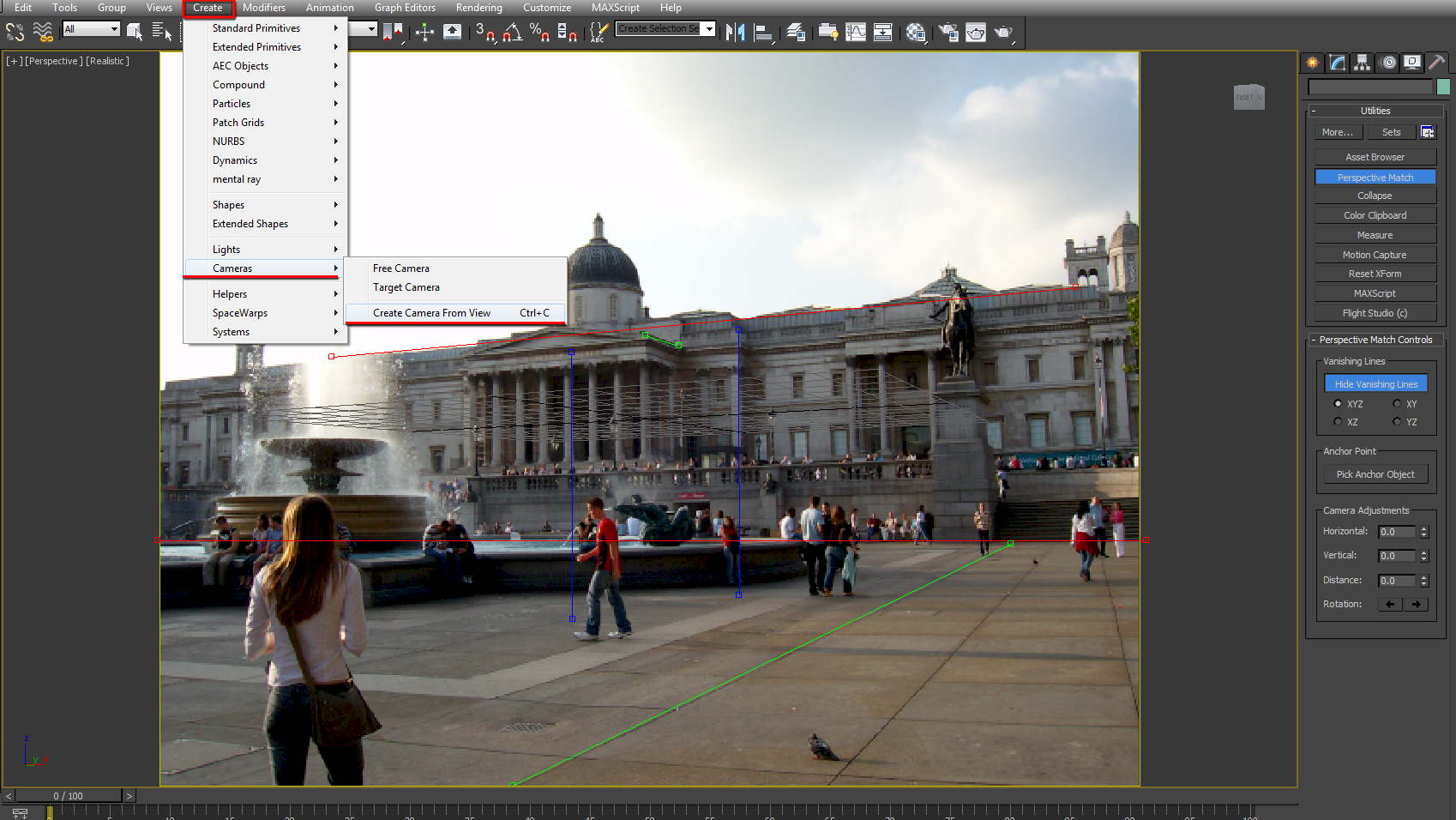
Create Camera From View
As mentioned earlier, since cameras are often at eye level (e.g. 1.65m), one can create a surface (e.g. Box- geometry standard primitive) 1.65m below the camera, and increase its width and length to fit the dimensions of the photo reference.
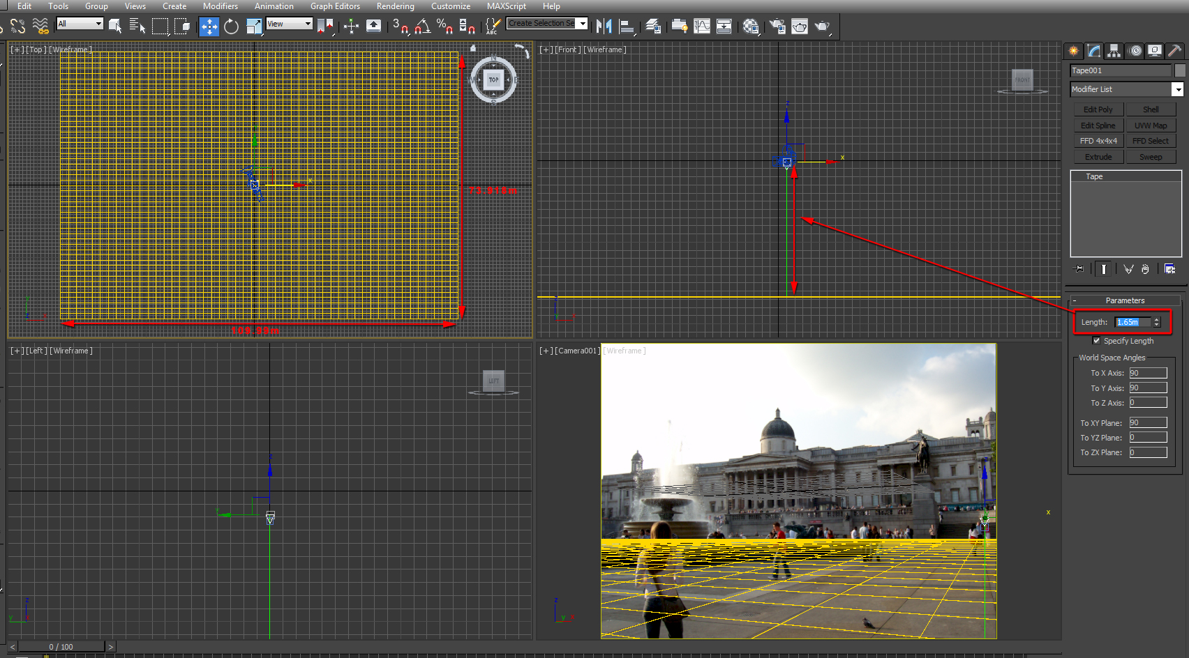
Create a surface 1.65 m below the camera
From this point onwards, one can create other reference points such as people and other objects in the scene.
Since a standard 3ds max camera is currently being used in the scene, one can recreate a similar VRayPhysicalcamera manually or via a script camera converter.
Alternatively, simply keep the current standard 3ds max camera, and open the Environment and Effects dialog (8).
In the Exposure Control rollout parameters, load the VRay Exposure Control option from its dropdown list.

Load the VRay Exposure Control
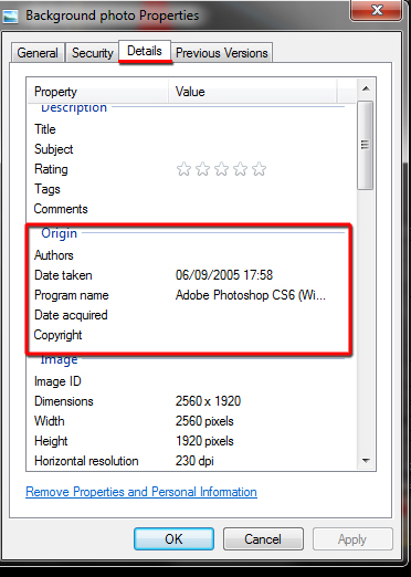
Use the background photo Properties Details to enter more accurate camera detail parameters such as Focal Length, F-stop, ISO speed, etc.
The Origin info from the Properties Details can be used in the Daylight System parameters (chapter 3) to enter the time, day and location of the photo taken.
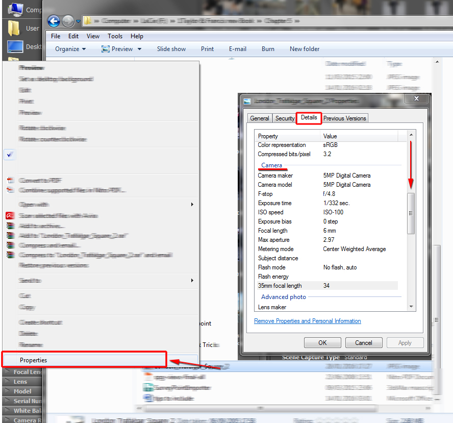
Background photo Properties Details
For aerial shots looking down; the previously described methodology might not work. Instead users might have to eyeball the correct camera perspective, by constantly rotating, moving and tilting the camera accordingly.
It often takes a bit of practise to camera match aerial shots accurately.
Integrating shots in 3ds Max
Prior to starting, ensure the background photo is plugged into the Environment Map toggle, and that its Mapping coordinates is set to Screen type.
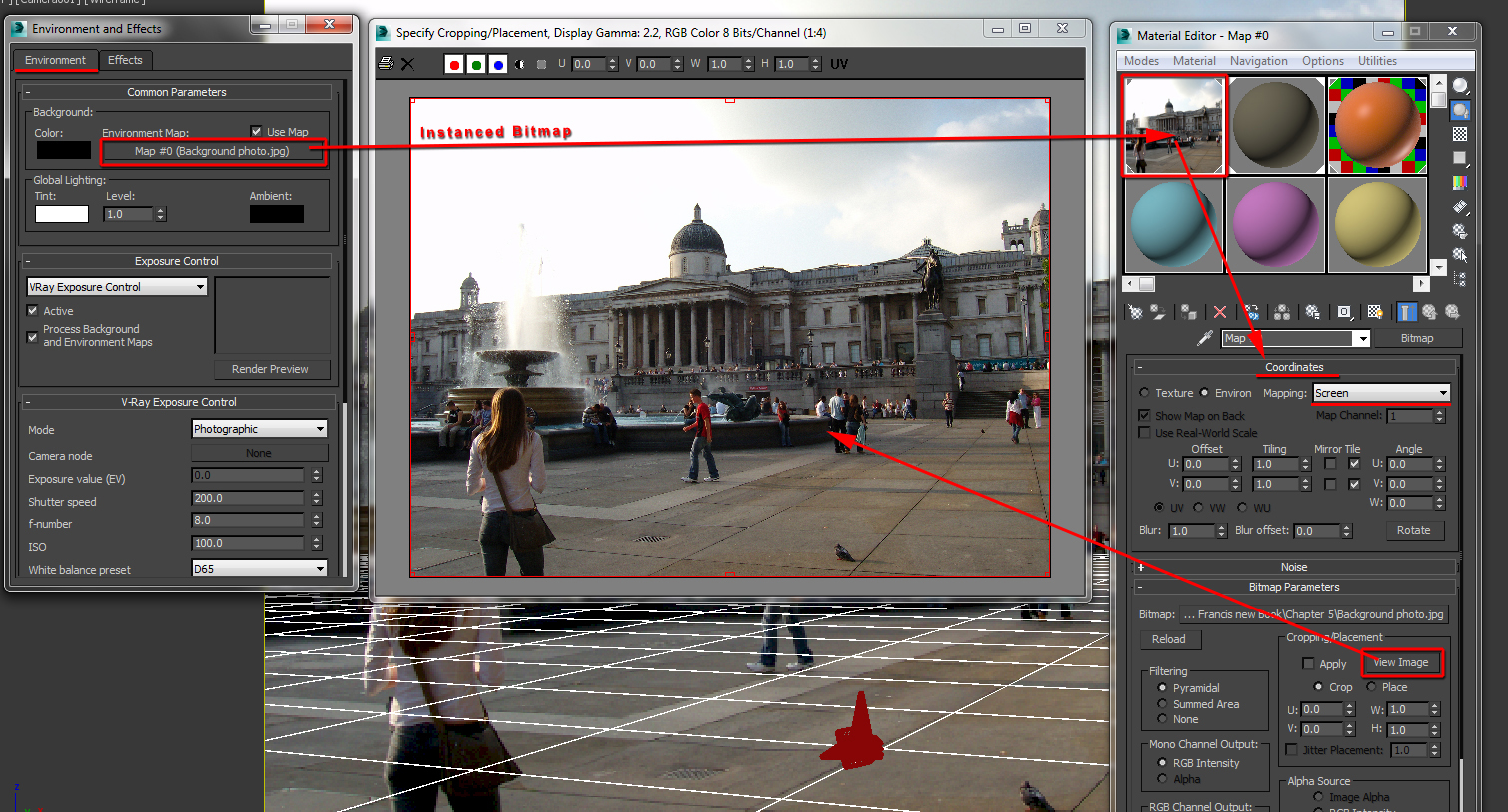
Background photo plugged in the Environment Map toggle
In the Color mapping rollout parameters, ensure the Affect background function is disabled.
This function will prevent the environment background photo from being affected by the GI and the VRayPhysicalcamera settings (e.g. prevent it from being washed out, overexposed; etc).
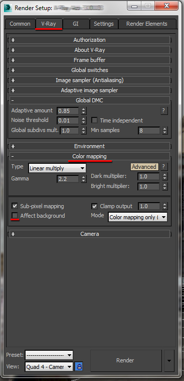
Affect background disabled
Next, ensure the Enable GI option is turned on.
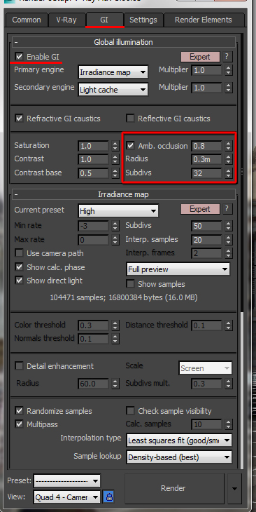
“Enable GI” option is turned on
If the 3d surface/ground in the scene is to be used as a Matte object to cast shadows; simply do the following:
Select the surface in the scene and right click on it to bring up its quad menu. Select the V-Ray properties option, to open its dialog.
In the Matte properties group, enable the Matte object option and set the Alpha contribution to -1.0.
The value of -1.0 will ensure the 3d surface is not included in the alpha channel.
To have shadows cast onto its matte surface, simply enable the Shadows option in the Direct light group, and Close the dialog.
After closing the dialog, apply a VRay material similar to the ground surface seen in the background photo.
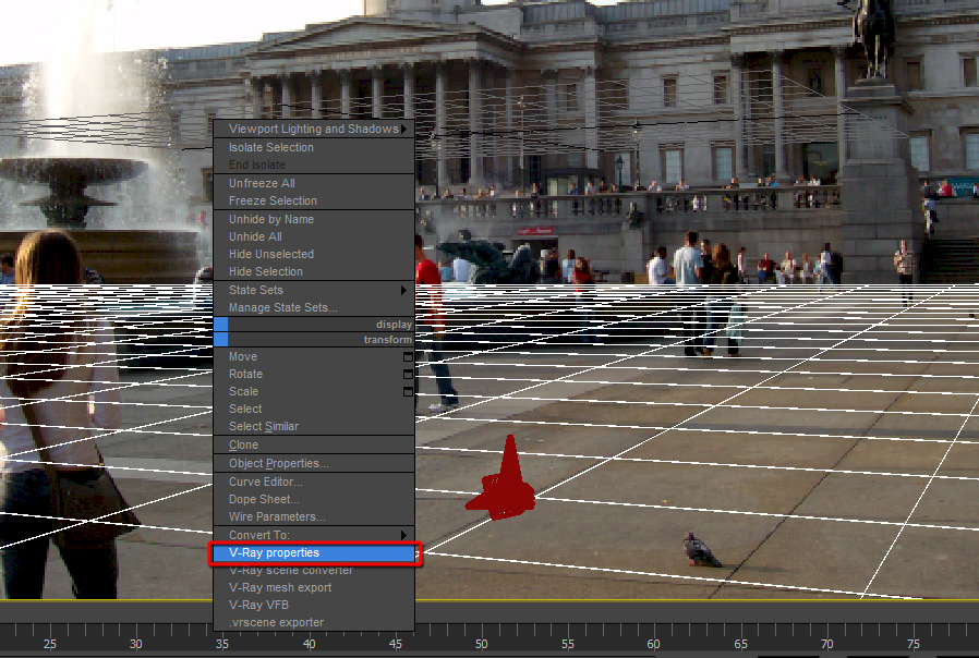
Select the V-Ray properties option
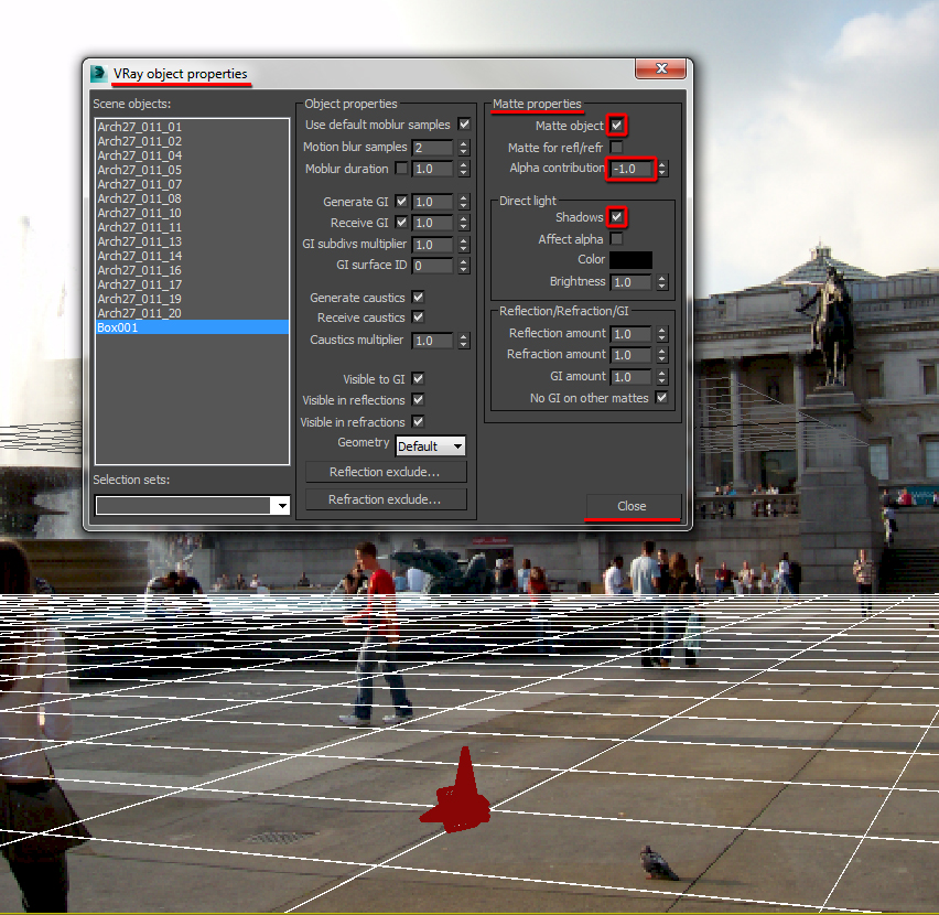
VRay object properties dialog
If it’s a daylight shot, ensure a daylight system object is created and the date and time information is accurately entered in its parameters, as previously covered in chapter 3.
It’s utterly imperative to enable the Daylight Saving Time option.
Also, the daylight compass should be placed on the same level as the ground.
Origin Properties Details
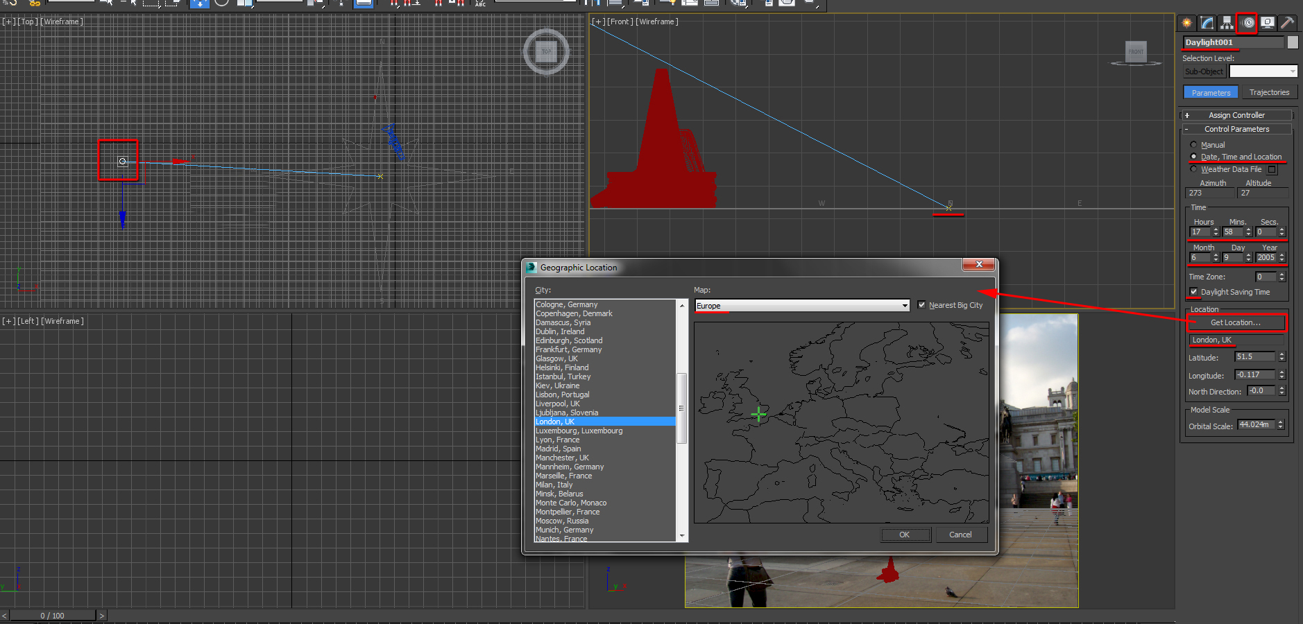
Daylight System position and parameters
To prevent the 3d orange cone in the scene from color bleeding onto the Matte object surface; a VRayOverrideMtl needs to be applied onto the original material.
A VRay black material (or similar) should be plugged into its GI toggle. For more information about this procedural map, refer to Chapter 2.
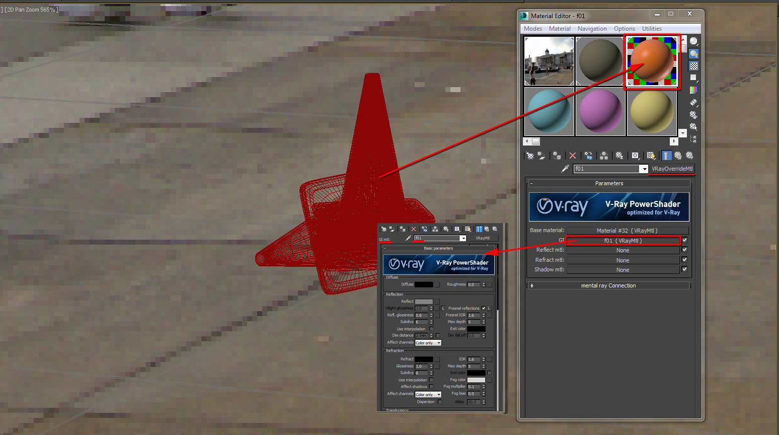
“VRayOverrideMtl” applied
Also, to make its indirectly lit areas slightly darker; simply open its VRay object properties dialog and set its Receive GI value to about 0.1.

Receive GI value set to 0.1
Next, create a VRay dome light and increase its Intensity value until the shadow colour is matched with the background photo.
Tweak with its Color temperature; or simply sample it from the background photo in the viewport.
Alternatively, plug an HDRI to the dome light as depicted in chapter 3.
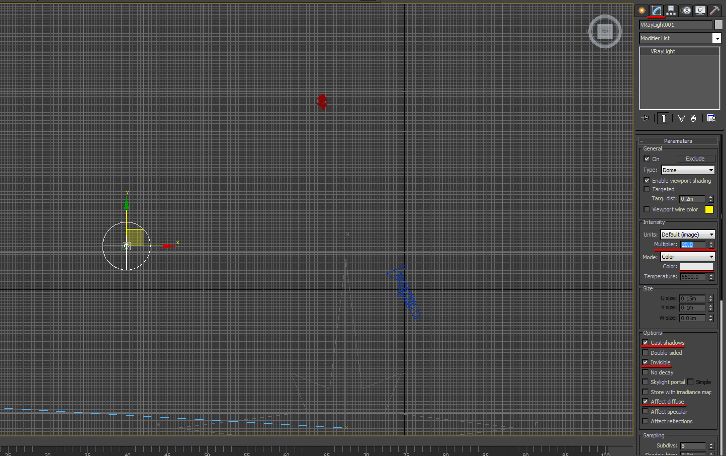
VRay dome light parameters
Shadow brightness matched, by increasing the VRay dome light “Intensity Multiplier”
If it’s a Night shot, the daylight system object needs to be deleted or disabled.
By default the 2d reflections/refractions in the scene come from the Environment Map toggle.
To override this, simply open the Environment rollout from the Render Setup dialog and enable the Reflection/refraction environment option.
Following that, simply plug a different bitmap or an HDRI (spherical mapping coordinates type) to its toggle. Refer to chapter 3 to see how an HDRI can be used.
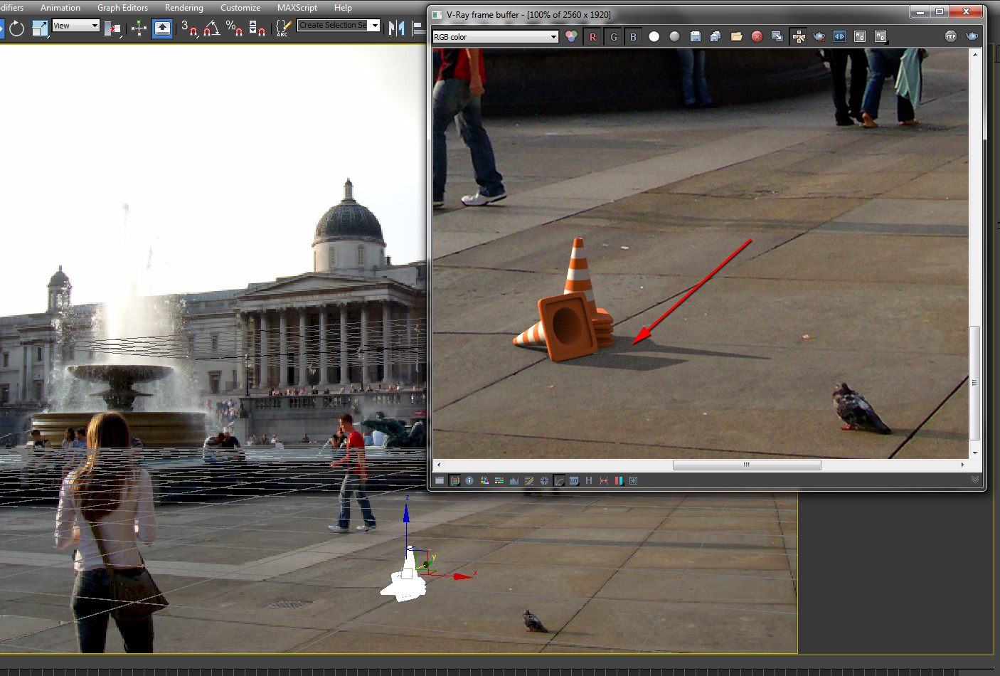
To seamlessly match the bright highlights of the render with the background photo, simply go to the Color mapping rollout parameters and increase the Bright multiplier to about 1.8, or higher.
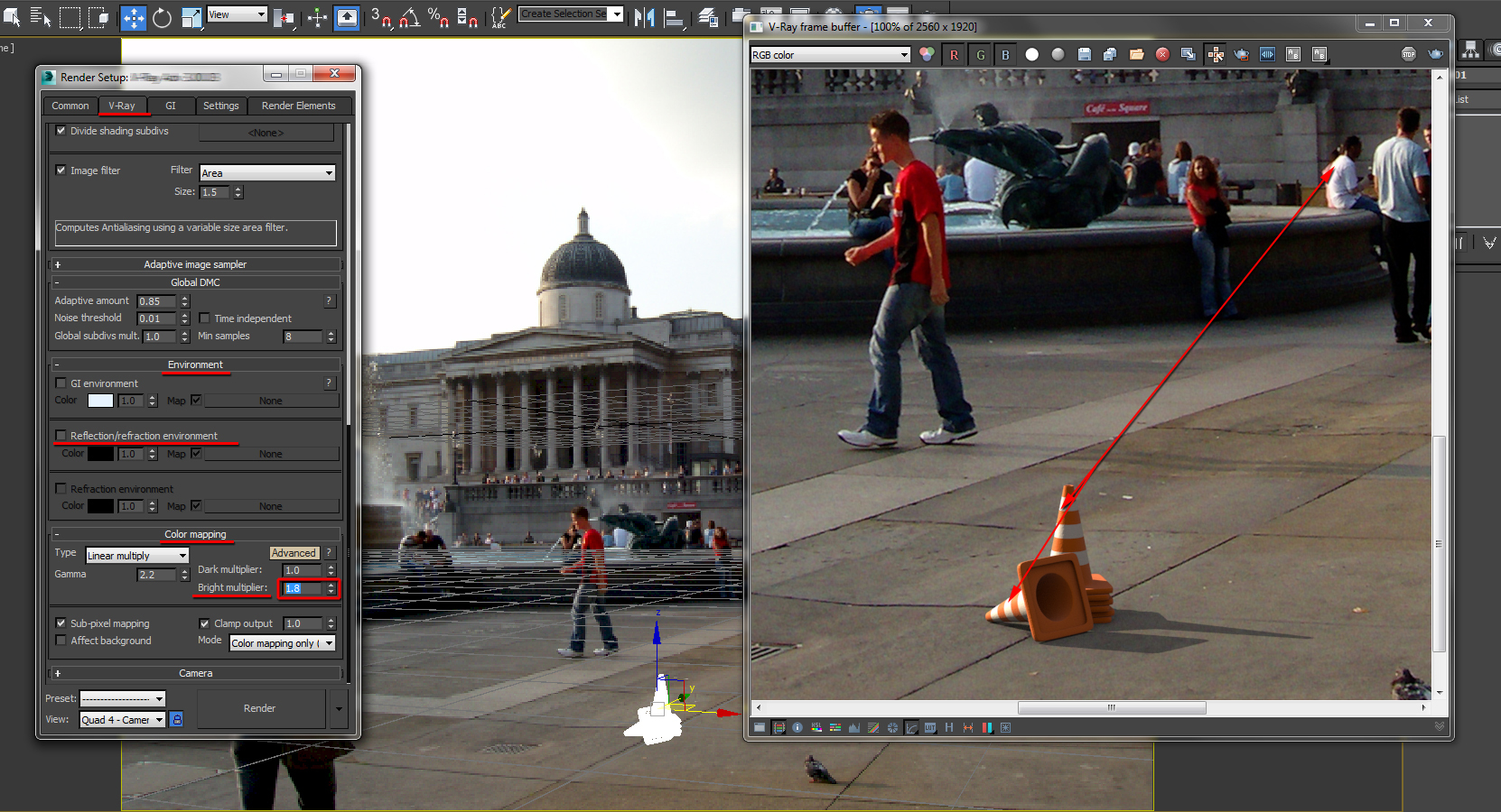
Increase the “Bright multiplier” value to about 1.8
< Increase the Bright multiplier value to about 1.8>
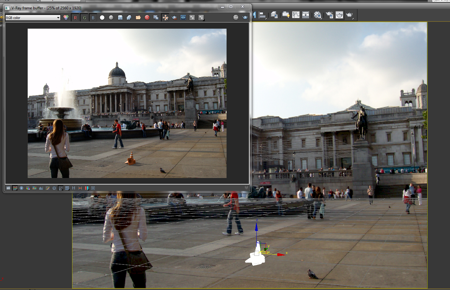
Final render
To populate the scene, you can simply go to gobotree’s extensive library of cut out people, ready to be dropped in the scene.
To do so, simply type in, cutout, from the their search box
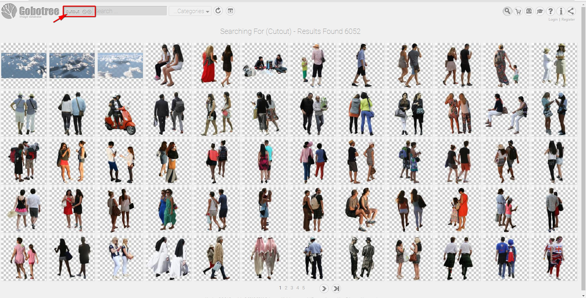
Gobotree cutout people
Exclusively for Gobotree – Jamie Cardoso


Pingback: Visual Eyes Media | Camera Matching Tutorial